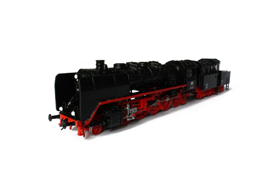
As I wrote a while ago, I received a very nice little
H0 steam locomotive for my birthday from my friends, the
American 4-4-0 Baltimore & Ohio no. 822, manufactured by Mehano. I soon bought some
H0 tracks and a Piko speed and direction controller and started testing the locomotive. To my great disappointment, as seen
here, there were two main problems generated by the incompatibility between the locomotive and the power supply (the Piko speed and direction controller):
1. The locomotive produced a pretty bothering buzz, especially at low speeds.
2. The locomotive seemed to run strangely at low speeds, more like jumping on the tracks instead of rolling continuously.
At the time I had no idea what the problem was, but with a lot of help from my friends at the
forum.lokomotiv.ro railway forum, I soon understood that they were caused by this incompatibility between the locomotive and the power supply. They explained to me that the buzz was produced by the engine because the Piko power supply was giving it
PWM current at very low frequency (around 170 Hz). So I set out to build a homemade power supply that could supply
PWM current at a frequency higher than the human ear can perceive (higher than 20 KHz). The other option would have been to just use normal DC, but the advantage of
PWM current is that the maneuverability is greatly increased when the locomotive is running at low speeds, making operations like shunting possible.
I built my homemade
PWM power supply based on the following circuit diagram:
Additionally, I added a diode bridge (rectifier) and a 4700 microF 25V capacitor to the input to transform the AC input into DC (I did this because I used the AC power supply that came with the Piko speed and direction controller, but this can be omitted if the input power is DC). I also added two colored LEDs, connected in parallel with the tracks (in serial with a 1 KOhm resistor) to indicate the output current's polarity and the locomotive's running direction and a 4.7 nF capacitor connected in parallel to the 0.1 microF capacitor to switch between buzz-free mode and greater maneuverability mode. The parts not present on the circuit diagram are listed with non-bold (regular) font below.
Used parts:
IC1: CD4093 (using 2 gates with NAND-Schmidt trigger from it - contains 4 such gates)
IC2: LM7809 (voltage regulator)
Q1: BD651 transistor
Q2: BC547 or BC172 transistor
C1: 1nF capacitor
C2: 0.33 microF capacitor
C3: 0.1 microF capacitor
C4: 4.7 nF capacitor
C5: 4700 microF 25V capacitor
D1 and D2: 1N4148 diodes
D3: 1N4007 general usage diode
DB1: diode bridge (rectifier) for about 12-15V
R1: 2.2 KOhm resistor
R2: 2.7 KOhm resistor
R3: 0.68 Ohm resistor
R4: 1 KOhm resistor
P1: 100 KOhm potentiometer (linear or logarithmic are both fine)
LED1, LED2: different color, standard 3mm LEDs (any standard LEDs will do) to indicate direction
SW1: direction switch - double switch to inverse output current polarity with a single move
SW2: maneuverability switch - any kind of switch to couple/decouple C4 in parallel with C3
After about two weeks of work, my power supply was finished. I wrapped everything into a nice plastic box, leaving only a few things out: the direction switch, the maneuverability switch, the direction indicator LEDs, the speed controller potentiometer, the input jack and the output cable. The
input is AC 12V (theoretically DC is also OK and voltage values close to but not exactly 12V should also be fine), the output is
PWM current. The direction switch is used to change the polarity of the output current, thus making the locomotive change its running direction. For visualizing the output current's polarity (the locomotive's running direction) I coupled a blue and a yellow LED in parallel with the tracks (serial connection with a 1 KOhm resistor). As I found out during the making of the power supply, there is no golden solution which makes the buzz go away and also offers great maneuverability, only compromises. This is why I introduced the maneuverability switch, which couples/decouples a second capacitor (of 4.7 nF) in parallel with capacitor C3. When the second capacitor is on (coupled), the locomotive can be controlled very precisely but the frequency of the output
PWM current drops below 20 KHz and becomes audible. When this second capacitor is off, the buzz cannot be herd but the maneuverability is affected (however it's still better than with the Piko speed and direction controller!).
So here is a video which demonstrates the differences between the Piko speed and direction controller and my own homemade
PWM power supply:
And a few pictures of how it looks on the inside:
Special thanks to
mpursu and
dac members of the
forum.lokomotiv.ro railway forum! Without their help this project would have not been completed.
Links:


 IQ Jar - Put your mind into it!
 Nail Glaze
 The Must Blog
 Gyávol Roland Photography
 Ötletfészek


